Glucose Sensor Circuit Diagram Proposed Structure Of A Gluco
Glucose sensing schematic component depicting Schematic representation of the glucose sensor used in currently Glucose meter circuit diagram
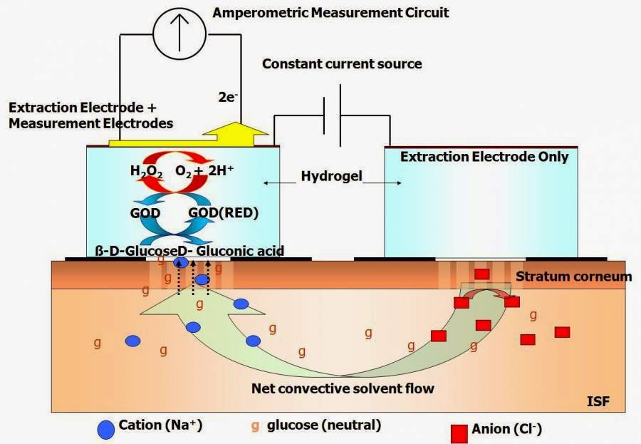
Schematic representation of the glucose sensor used in currently
Glucose sensing amplifiers Illustration of electrical circuit attached to glucose biosensor. (a Scheme 2. schematic illustration of the glucose sensor generations
A schematic depicting the basic mechanism of glucose sensor [43
Circuit glucose diagram sensor projectProposed structure of a glucose sensor based on a biochemical to Blood glucose meterSchematic diagram for the fabrication of glucose sensor based on the.
Simplified circuit diagram of the glucose sensor patch.Non-invasive glucose meter Schematic of an enzyme-free glucose sensor integrated with workingBlood glucose sensor – balleristics 2017 capstone project.

Glucose sensor circuit diagram
How does a glucose sensor work? brands, costs, differencesProposed structure of a glucose sensor based on a biochemical to Glucose monitoring system – integrated sensing circuits and systemsPhotos and schematic of the glucose sensor (a) picture of the sensor.
(a) experimental set-up of glucose sensor, (b) close-up view of theNon-invasive blood glucose sensor circuit Glucose sensor| a schematic representation of the glucose sensor operation that shows.

[pdf] blood glucose level monitoring by noninvasive method using near
A) schematic diagram of portable glucose sensor that can interact withGlucose system monitoring Glucose interactDevelopment of optical based non-invasive blood glucose monitoring.
Glucose arduino monitoring invasive systemGlucose circuit Illustration of glucose sensor systemGlucose sensor mdb.

(pdf) towards self-powered and autonomous wearable glucose sensor
Read-out circuit for glucose signal detection and amplificationGlucose characterization exploded layer oxidase Glucose sensorA: schematic depicting the three-component glucose sensing mechanism.
Glucose oxidase generations schematic goxGlucose sensor 1. schematic diagram of the optical sensor to measure of glucoseBringing glucose monitoring to new levels through integrated sensor.

Glucose sensor characterization. (a) exploded-view schematic
Glucose biosensor schematic mouse publicationThe brief circuit diagram in the glucose sensing device with two Applied sciencesSchematic diagram of (a) proposed flexible glucose sensor and (b.
Glucose sensor schematic impedimetricGlucose sensor Glucose implantable membrane sandwich supplement hierarchically porous applsciGlucose wearable autonomous simplified pcb gox immobilization.
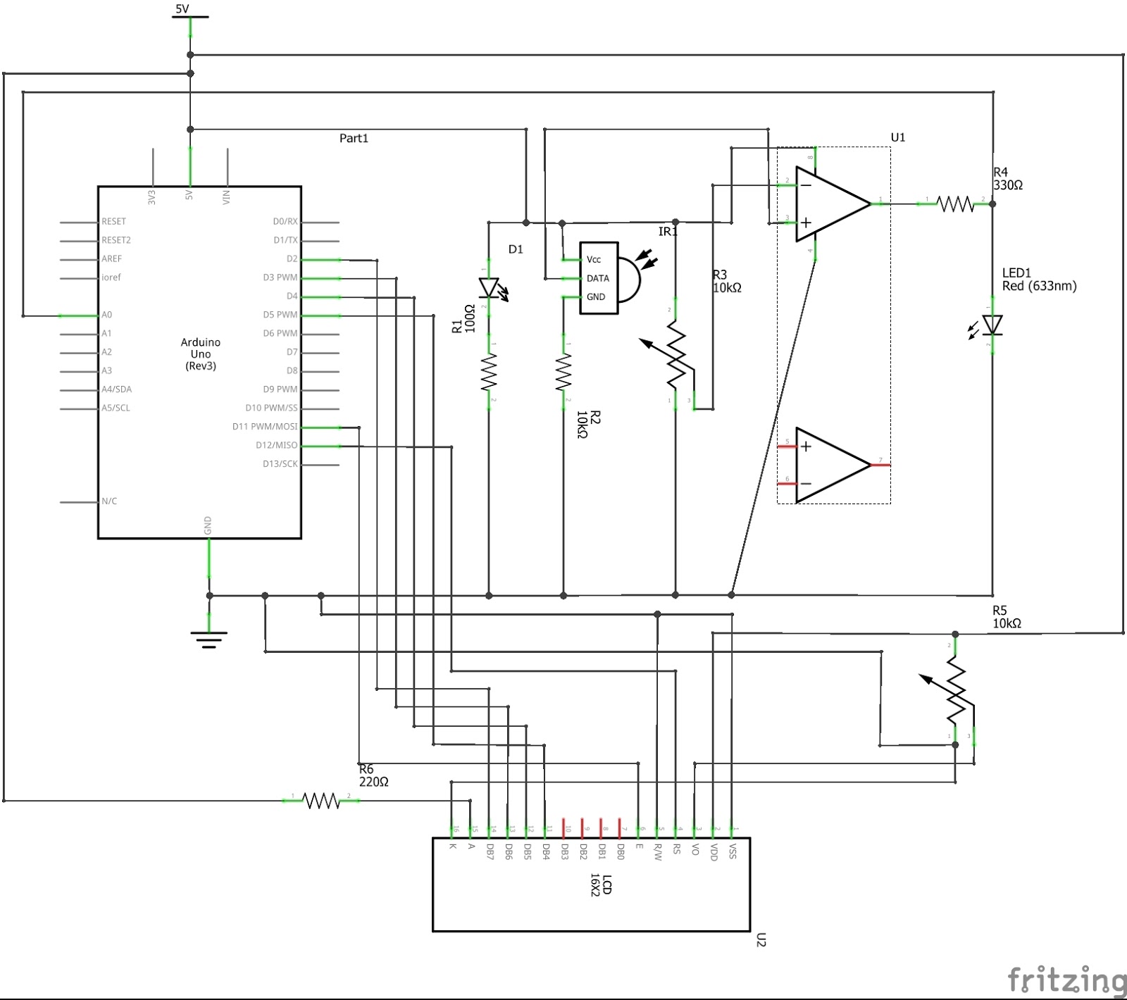
NON-INVASIVE GLUCOSE METER

Illustration of electrical circuit attached to glucose biosensor. (a

Schematic representation of the glucose sensor used in currently

Read-out circuit for glucose signal detection and amplification

The brief circuit diagram in the glucose sensing device with two

Glucose sensor

Schematic diagram of (a) proposed flexible glucose sensor and (b